Precision work in Blender
ByWithout pretending to be a cad drafting tool, Blender has more precision functions than people usually believe. Everything can be built with the greatest accuracy. I really value this and it was a decisive point when switching to Blender as my full time modelling and visualising tool.
I used to model in cad software so I had high standards and for some time did feel rather frustrated with the differences and difficulties. One challenge was the lack of specific documentation: I couldn’t find all info I needed in one place… or any place… and I believe that is still the case today, even though more professionals, many architects among them, are starting to use Blender and more information is to be found on the net. The Blender official wiki is a very well written resource but for the Blender first timer could be a little difficult to navigate it and find the relevant chapters, so here is an attempt to put together the info drawn from my own experience with precision work in architectural modeling in Blender. This post is more like a listing of the useful functions, meant to be followed by a second post with some “hands on” examples.
Topics:
- using units
- 3d axis
- keyboard numeric input and axis constraints
- manipulators
- the transform properties toolbox
- numeric input for modifiers
- 3d cursor
- object origin
- object snap
- grid snap
- snap menu
- show edge lengths
- pivot point, using an “empty”
- transform orientations
- align
- align rotation with the snapping target
- divisions
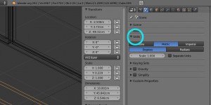
The first important step for precision work in architectural modeling is noticing the Units. I work in meters: 1 blender unit = 1 meter. To do this it’s not necessary to change the default units settings but you can go to the Scene Panel in the Properties window so you can have the units properly displayed, most convenient for those who use Imperial units. This feature was not here before Blender 2.5 version.
To bring reference to scale in a Blender file, check this posts: importing dxf drawings, importing cad plans as images
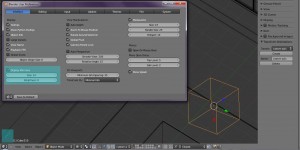
You can choose to keep or not a representation of the 3D global axis in the bottom left corner of the 3d Window to remind you anytime how your world is leaning, through the User Preferences window:
Seems the icon keeps to the global axis no matter what axis system you are using. More on changing the coordinate system below.
Keyboard numeric input and axis constraints
Transformation actions in Blender – translation, rotation, scaling, in both object and edit mode – can be constrained along the x,y or z axis by pressing the corresponding keys: x, y, z. After pressing the constraint key, numeric input can be directly entered on the keyboard. If you enter numeric input without first entering a constraint, by default Blender constraints the action along the x axis.
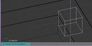
Example: to move 2.4 m on the z axis select the object and press in sequence G z 2.4 enter. Mouse and keyboard actions are dynamically displayed in the lower left corner of the 3D window:
Alternatively, if you don’t need to be precise to a digit, you can press the constraint key and just move the mouse following the values displayed in the left corner. By pressing shift while doing this, you’ll be able to change the value in smaller increments.
Pressing MMB after a initiating a transformation is another way to activate constraints, just move the mouse near the axis you need.
Another type of constraint is created by locking an axis. Press Shift+z for instance to lock the z axis and move or scale just in the xy plane.
Extruding (edit mode) is followed by default by a translation action on which you can use constraints and numeric input.
Manipulators are a shortcut for transformations + axis constraints. Instead of selecting an action, then the constraint, with the manipulator activated you just grab the manipulator icon by the needed axis, then proceed with the numeric input.
You can check just one of the three manipulators (for translation, rotation or scale) or any combination between them. To select multiple click shift+lmb on the icons in the 3d window header.
The Transform Properties toolbox
In the 3d window, pressing N will open the Properties toolbox, docked on the right side of the window:
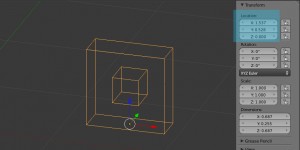
In this area you can set the exact size of an object, it’s location and rotation. When switching to edit mode the toolbox changes a bit to show the location of selected elements.
To change the values in the numeric input boxes you can click to write the numbers on the keyboard then press “enter”, or you can scroll with LMB, best holding shift pressed too.
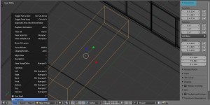
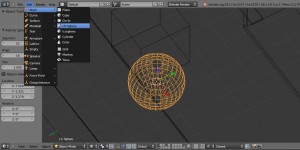
Part of this data, location and rotation, also make a short appearance when creating a new object, in the Tool Shelf (docked on the left side of the 3d window, press T to open it). This option disappears soon after clicking anywhere else outside this panel and getting on with your work. However, this area doesn’t seem to bring more to the game than the Properties Shelf except in the creation of spheres, where you can set the number of faces:
After changing size you should apply the transformations – scale and rotation – using ctrl-A. If you don’t, bad things will happen when using modifiers and some other stuff.
The following modifiers are so useful in architectural modelling and they come equipped with numeric input: array, mirror, bevel and solidify (some details on the latter here).
These modifies are perfect for the precision lover. Not only for the numeric input but for the fact numbers can be changed at any time unless the modifier is “applied”. Array also comes with a “merge” option that makes arrayed objects to lock nicely one to another, no overlapping parts. The mirror modifier has no true numeric input but it is a precision tool, as the mirroring axis is the object’s origin or another object that can be precisely positioned and it also comes with merge and clipping options.
This intriguing red-white circle like a little target in the Blender 3D view usually annoys newcomers because they start clicking with the LMB trying to select stuff the way they do in other software and instead of selecting, this thing keeps appearing under the mouse click 🙂
The 3D cursor is a helper point you can use a great deal in precision work and its functions are scattered around Blender. It’s not an object so you can’t move it as you do other Blender stuff.
Ways to place it in the 3d space:
- Shift+C moves it to the origin of the axis coordinates.
- LMB click moves it (with no precision though) anyplace in the 3d space.
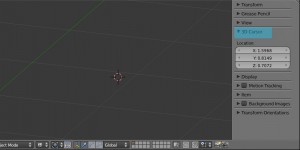
- In the Properties panel -> 3D cursor tab you can numerically enter it’s 3d coordinates:
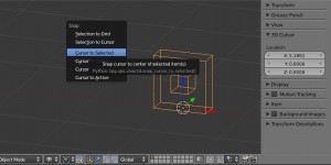
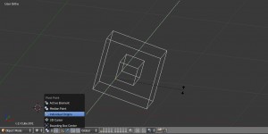
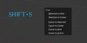
- Stick it to a selected vertex, or selected object origin, by way of the Snap Menu brought up by Shift+S.
Ways to use it once it’s properly placed:
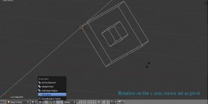
- It can be set as a pivot point in the 3d window header and used in rotations, scaling, mirrors:
- You can snap something to it in object or edit mode, again by way of the Snap menu (Shift+S)
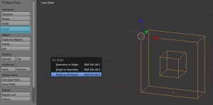
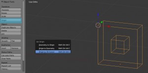
- You can use it to change an objects origin in the Object Tools tab, found in the Tool shelf docked on the left of the 3d window (T):
(or if you are an extreme shortcut fan you can easily use Shift+Ctrl+Alt+C :D)
- New objects are created at the cursor location.
- You can use it as a pivot for the spin function:
This is shown as an orange dot and is sort of the insertion point for the object, not the same as the geometrical object center.
The location coordinates of an object shown in object mode in the Transform tab of the Properties panel are it’s Origin’s coordinates.
For newly created objects the origin is placed in the geometrical center. You can change it’s position anywhere in the 3dspace relative to the object from the Tool shelf docked on the left of the 3d window (T) or from the menu brought up by the amazing Shift+Ctrl+Alt+C shortcut:
I don’t think there is a way to directly input coordinates to change the origin position, but you can position the 3d cursor where you need the origin to be, as shown above in the cursor paragraph, then set “origin to 3d cursor”. Setting the origin only works in object mode. One thing I often do is going to edit mode to snap the cursor to a vertex of the object, then go back to object mode to move the origin to the cursor.
The origin can be used as a pivot point for mirroring, scaling, rotating.
Examples of use:
You might want to set the origin of objects that “sit on a floor”, like furniture, at the base of the object, so when scaled they keep their feet on the floor and you don’t have to readjust their z position.
In some cases, when handling a set of objects, setting all origins at the same point might be of help.
The mirror modifier uses the object’s origin to place the mirror axis.
It’s a snap to use snap in Blender 🙂 Well, there are a few drawbacks if you compare with cad software but I’ll start with the good news.
Snap functions work both in object and edit mode. There is a snap on/off button and several snap options in the 3d window header:
One way to work with snap without having it always active and getting in the way, or having it on/off too often, is to keep the snap button unchecked and press Ctrl when you want to snap. Or the other way around depending on what you do, keep snap button on and press Ctrl during the actions you don’t need snap for.
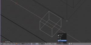
The snap settings I use most are snap to vertex + closest. This makes the moved object or selection snap to the target by it’s closest point, this is usually what I need as in my projects things usually tend to align side by side. For this to work, the object moved must be first positioned on the proper side of the target.
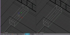
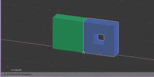
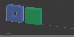
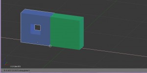
I feel this needs an example. I want to move the blue box, that is now placed to the right of the green one, to it’s left. Now it will snap nicely to the right side of the box:
Going with the mouse to the left side of the green box will not give the wanted result:
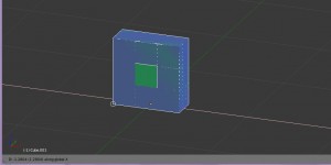
So first the blue box has to be moved to the left without using snap:
Then it will snap well to the green box with the side that is closer:
“Active” uses as snapping point the active element, that is, the last picked in the selection (Blender shows this highlighted in a lighter orange). I find this more useful in edit mode, when you want to snap an element by a vertex that is not on the bounding box of the selection and will not work with “closest”.
I find it a good idea to use snap while using constraints, gives more control in complex setups.
Experimenting with snap options will give you a better grasp on its use.
Snap limitations: some actions don’t work with snap, like cutting loops (in the process of cutting a loop snap doesen’t work though I usually wish it did and save me some extra clicks). I also didn’t get the snap to work correctly with constraints in a custom axis system. Sometimes, as far as I noticed when dealing with more complex objects, some points fail to react and snap, looks like a bug. Usually works if you insist: wait a bit while holding the mouse over the point, zoom in closer or change the viewing angle.
Though this is a popular drafting feature and works in Blender, I don’t use it much. Maybe my projects are never that well behaved so they would fit a grid or maybe I just never got used to it. But I’m sure many use it and it’s a very good precision feature.
You’ll find grid settings in the Properties panel -> Display tab, and you can set the snap to work in grid increments:
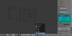
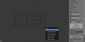
This doesn’t actually snap the object or vertex to the grid but moves it in grid increments from the current position. To go on the grid you’ll first have to bring up the nifty extra Snap menu by pressing Shift+S and go to “snap selection to grid”:
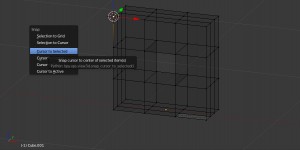
The snap menu works in both object and edit mode and it’s brought up by pressing Shift+S. It allows various snap options between the cursor and selected objects:
You can also find this in the object menu in the 3d window header but using the shortcut seems easier.
See also the Cursor and Grid paragraphs above.
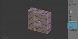
When in edit mode, Blender can dynamically display edge lengths, angles, surfaces on selected elements. You can switch this cool feature from the Properties panel on the right side of the 3d window (N), from the Mesh display tab:
There are not too many options for displaying the numbers so if you have all the mesh selected it will be difficult to read them. Sometimes the axis or cursor get in the way. I use this mainly to check measurements, by selecting just enough vertices.
One important thing to remember: numbers will not show right if the object has been manipulated in object mode and transformations not applied. Apply scale! (Ctrl+A)
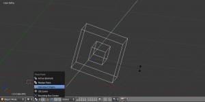
Pivot point setting is found in the 3d window header.
See the 3d cursor and object origin paragraphs for ways of setting the pivot with precision.
This is equivalent to cad “change UCS”. I got stuck for a while with my first Blender project because after I test modeled a rectangular building and decided “it’s a breeze”, of course client sent a plan with non-90 degrees angles and I was lost.
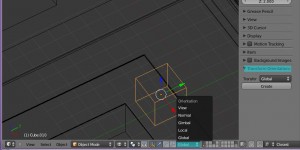
To change between various axis systems (like Global and Local) or create a custom orientation when your project is not all that orthogonal, use the Transform Orientations panel in the Properties panel (shortcut N) or the Transform Orientations drop down from the 3D window header. Rotate a cube (or any object created in the global axis system) to the desired new axis orientation, and keeping it selected press “Create”; then you can name and save the new axis orientation and select it when needed (no need to keep the rotated object).
To use axis constraints in a custom orientation you’ll have to press twice the axis shortcut: xx to move on the new axis, yy, zz.
Snap + axis constraints should work in custom orientations too but in practice they don’t (snaps but not the way I expect). Maybe I am doing something wrong, would be happy if someone could help me with this one.
There are two other nice precision tools hidden in the Object menu in the 3d window header. I didn’t find a shortcut for these, not even a five-fingers-and-one-toe one.
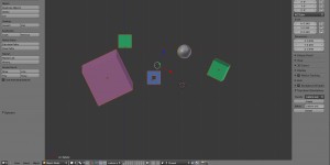
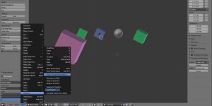
In case we got some architectural objects scattered like this all around the project we can select them and…
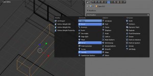
…go to the object menu:
“Align to transform orientation” gets them all neatly aligned to the current axis system.
“Align objects” opens the Align objects tab in the left side Tool Shelf (T), with several options for choosing the alignment plane and the alignment point for the objects.
In edit mode I couldn’t find a dedicated tool for aligning vertices on a plane but it’s easy to do it by scaling with zero value on the selected axis. For instance, to align a selection of vertices on a xy plane you press S-Z-0.
Align rotation with the snapping target
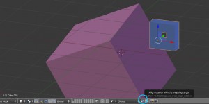
This is an option that appears in the 3d Window header next to the snap settings:
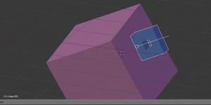
It works only in object mode, with move (grab). When snapping, it should align objects to the snap target’s normals. From what I make out of it, it’s useful if you set the snap to “faces”, you will be able to align the object to a face on the target object. In the example above, this is the result:
Wiki on snap and align rotation
You might need to divide something in equal parts. This can be done in edit mode in two ways. One is the Subdivide in the Specials menu that you bring up by pressing W (edit mode). A panel will form in the Tool shelf (T) on the left, where you can enter the number of cuts that will subdivide the selected elements.
It’s better to use subdivide on the entire object (all faces selected) or else your object will be cut in a bad way, with lots of triangles that are difficult to edit later. I will edit this part after B-mesh is in the official release.
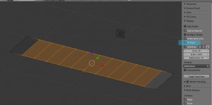
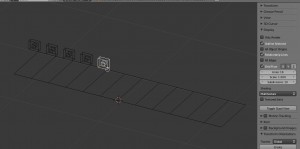
The second, even nicer method, is by cutting multiple loops. I’m not getting into loops right now, but I see this can be used as a nice precision tool so I added it to the list. In edit mode, after starting the cut (ctrl-r) scroll the mouse wheel and you’ll get multiple loops equally spaced. You can divide an object or make a helper object with the divisions you need, to which to snap. In this case, you have to turn on “show all edges” in the Properties Panel -> Display tab so the divisions show up when back in object mode:
You now have divisions to snap to:
There are times when this is faster and serves the purpose better than using arrays.
…..
……this has been a long post and I hope I managed to put it in a coherent form. Feedback and editing suggestions welcome. This will go into the “How to” section so should look it’s best 🙂
Maybe you are using something in your work flow that I missed? I would be glad to add to the list.



Pingback: Andreas' Blog » Blog Archive » Blender()